Description
Introduction of PLC pressure pump control panel :
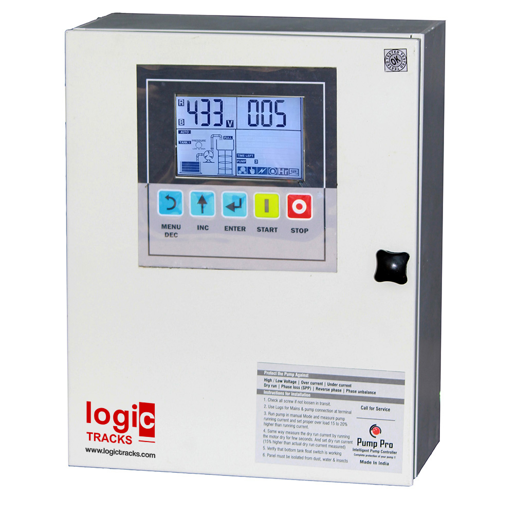
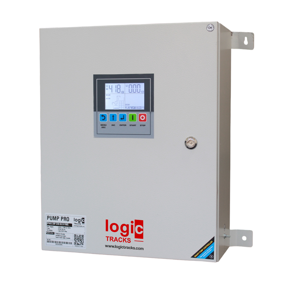
PLC Pressure pump control panel comes with 4inch Touch screen HMI & PLC mother board. This panel operates the pump on fix speed. It is available for 3phase 415v and single phase 230v for two pump cascading operation.
Pump can be automatically on/ff by pressure switch / float switch or by pressure transmitter. you can connect 4-20mA pressure transmitter for automatic on/off the pump on water demand. It has inbuilt real time clock so you can set particular date/day & time to on/off the pump.
Pressure transmitter can sense very small pressure drop hence you can use it for multi tower application. A common system can fulfil over head tanks of multiple tower.
A PLC Pressure Pump Control Panel is an integrated system designed to manage and automate the operation of pressure pumps using a Programmable Logic Controller (PLC). These panels are commonly used in industrial and commercial settings, such as water treatment plants, irrigation systems, oil and gas operations, and HVAC systems, where precise and reliable pump control is essential.
Key Components and Features :
1. PLC (Programmable Logic Controller):
– The PLC is the brain of the control panel. It is a digital computer used for automation of electromechanical processes. The PLC is programmed to monitor inputs from various sensors and control the outputs, which in this case are the pumps.
– It can be programmed to perform various functions like starting/stopping the pump, controlling pump speed, maintaining pressure levels, and protecting the system from failures.
2. HMI (Human-Machine Interface):
– The HMI is the interface through which operators interact with the control system. It usually consists of a touchscreen or display with buttons, allowing the user to monitor real-time data, change settings, and view alarms or notifications.
– The HMI provides visual representations of the system’s operation, including pump status, pressure levels, and flow rates.
3. Pressure Sensors:
– These sensors are critical for monitoring the pressure within the system. The data from the pressure sensors is fed into the PLC, which then decides whether to turn the pump on or off, or adjust its speed, based on the pressure requirements.
– Pressure transducers and switches are commonly used to ensure accurate readings and reliable operation.
4. VFD (Variable Frequency Drive):
– The VFD controls the speed of the pump motor. By varying the frequency of the power supplied to the motor, the VFD can adjust the pump speed to maintain a desired pressure level.
– This not only improves efficiency but also reduces wear and tear on the pump, leading to longer service life.
5. Relays and Contactors:
– Relays and contactors are used to control the electrical power supplied to the pump motors. They are activated by the PLC to start or stop the pumps based on the input from sensors and the logic programmed into the PLC.
– These components ensure that high-power circuits are safely and reliably switched.
6. Circuit Breakers and Fuses:
– These are safety components that protect the control panel and the pump motors from electrical faults such as overloads or short circuits.
– They ensure that in the event of an electrical problem, the system is safely shut down to prevent damage.
7. Enclosure:
– The control panel is housed in a durable enclosure that protects the internal components from environmental factors such as dust, moisture, and physical damage.
– The enclosure is typically made from materials like stainless steel or powder-coated steel, and it may be rated for specific environments (e.g., NEMA or IP ratings).
8. Wiring and Terminal Blocks:
– High-quality wiring and terminal blocks ensure reliable electrical connections within the control panel.
– These are carefully arranged and labeled to facilitate maintenance and troubleshooting.
9. Alarm System:
– An integrated alarm system alerts operators to any issues such as low pressure, high pressure, pump failure, or electrical faults.
– Alarms can be visual (lights) and/or audible, and they may also trigger remote notifications via SCADA systems.
10. SCADA Integration:
– Many PLC Pressure pump control panel are integrated with SCADA (Supervisory Control and Data Acquisition) systems for remote monitoring and control.
– This allows operators to oversee and control the pump system from a centralized location, even across multiple sites.
Operation:
– Automated Control: The PLC monitors input signals from sensors and makes real-time decisions to start, stop, or adjust the pump operation. This ensures the system maintains the desired pressure within the defined parameters.
– **Manual Override:** Most panels offer a manual mode where operators can override the automated control for maintenance or troubleshooting purposes.
– **Data Logging:** The system can log data related to pump performance, pressure levels, and any alarms, which is useful for maintenance planning and operational analysis.
Applications:
– Water Distribution: Used to maintain consistent water pressure in municipal or commercial water supply systems.
– Booster Pump Systems: Increases water pressure in high-rise buildings or large industrial plants.
– Irrigation: Controls the flow and pressure of water in agricultural irrigation systems.
– HVAC Systems: Regulates the flow of fluids in heating, ventilation, and air conditioning systems.
– Oil & Gas: Manages the pressure in pipelines and extraction processes.
The PLC Pressure pump control panel ensures efficient, safe, and reliable operation of pressure pumps, making it a critical component in various industrial applications.
Checkout our other product : Dual pump control panel
Check demo on : Youtube


Tanmay Shah –
Good product with good price with 4inch Touch Screen display.